


 English
 عربى
عربى Français
 Español
 Português
Cable tray straight adopts a coverless U-shaped straight section design, and the overall structure is simple and practical. Its core structure is a U-shaped trough, and the edges on both sides are des...
READ MORECable Ladder Installation: A Practical Guide to Supports, Accessories, and Assembly
If you are planning to install cable ladder for a new industrial project, the first decision is not which tray to buy. It is how you will support it. Wrong support spacing or missing transition pieces can cause sagging, cable damage, and failed inspections. In practice, a well-installed cable ladder system follows a simple rule: calculate the expected load first, then choose the straight sections and fittings that match the route, and finally secure everything at the recommended spans.
Before You Start: Load and Route Planning
Cable ladder installation begins at the drawing stage. The tray will carry both the weight of the cables and the mechanical loads from winds, vibrations, and temperature changes. Most industrial designs follow IEC 61537 or NEMA VE-1 to define safe working loads. A common approach is to select a ladder with a load capacity about 1.5 times the actual cable weight to allow margin for future adds.
Route planning matters just as much. Identify where vertical drops, horizontal turns, and branch-offs will occur. This is where the ladder accessories come in. A straight section cannot handle a 90-degree turn alone; you need a horizontal 90 elbow. A tee or a cross handles branch connections. A reducer handles a change in width. If you skip these fittings and try to bend the tray on site, you compromise the ladder's structural integrity and cable bend radius.
Key Installation Steps
Once the layout is approved, installation follows a repeatable sequence. The steps below reflect the typical practice on projects ranging from semiconductor facilities to data centers.
1. Mark and Set Supports
Support brackets form the backbone of the system. Use a level and a measuring tape to mark the locations on walls, ceilings, or floor stands. At each point, fix the bracket securely before laying any tray. A loose bracket will make the ladder shift during cable pulling and affect the final alignment.
2. Assemble the Straight Sections
Place the 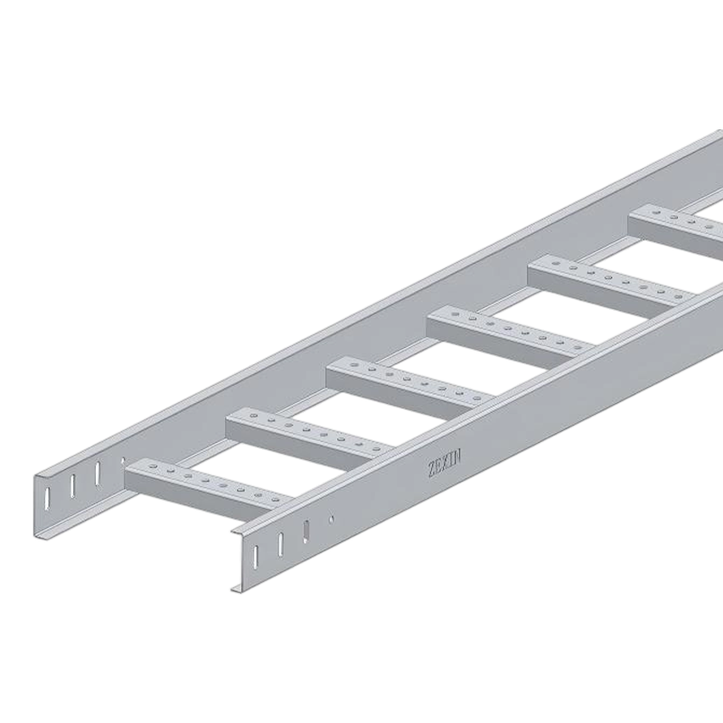 Straight Cable Ladder Section for Heavy-Duty Cable RunsThis straight ladder section provides a strong, lightweight support structure with 200 kg/m load capacity, ideal for high-density power and control cable installations requiring efficient heat dissipation.View Product → straight ladder sections on the supports, aligning the side rails. Connect adjacent sections using the appropriate couplers and their fasteners. When connecting two straight lengths, leave no visible gap. If the route requires a change of direction, add the corresponding fitting at the exact point where the ladder turns.
3. Add Elbows, Tees, and Crosses
For a 90-degree turn, install a 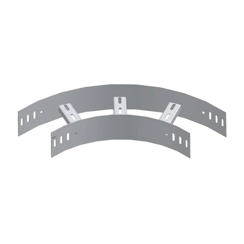 Horizontal 90-Degree Elbow for Ladder Cable Tray TurnsThis 90-degree horizontal elbow facilitates precise cable routing changes. Its inner bend radius of at least 300 mm protects cables from damage, and rung spacing ensures safe support.View Product → horizontal 90 elbow. For branching, use a tee or a cross fitting. Tighten all bolts but do not over-tighten; the fixing hardware should allow slight thermal expansion without stressing the tray wall.
4. Secure with Clamps and Bonding
After the ladder is in place, install clamps to keep cables organized. For grounded systems, the ladder pieces must be bonded to the building earth using the specified jumper straps. This is a frequent point in electrical inspections, so do not rely on the ladder rungs to provide continuous grounding.
Support Spacing and Maximum Loads
Support spacing is the most common installation error. Manufacturers publish load charts based on span length and deflection. In general, steel cable ladders with a 150 mm depth and 300 mm width support spans up to 3 m under normal cable loads. Heavier cables or seismic zones may require reducing the span to 1.5 m to 2 m. Reference the table below as a planning starting point; always compare it with the specific product data sheet.
| Tray width | Ladder depth | Max cable load | Recommended span |
|---|---|---|---|
| 200 mm | 100 mm | 50 kg/m | 2.5 m |
| 300 mm | 100 mm | 80 kg/m | 2.0 m |
| 400 mm | 150 mm | 100 kg/m | 1.8 m |
| 600 mm | 150 mm | 120 kg/m | 1.5 m |
These are indicative values, not a substitute for load calculations. When your installation includes multiple cables that generate heat, use the tray width to keep the cable fill ratio below 40% and provide enough ventilation.
Surface Finish and Environmental Considerations
The environment around the ladder dictates which finish you need. Indoor installations with normal humidity can use a standard galvanized finish. For outdoor or coastal projects, hot-dip galvanizing or powder coating provides a thicker protective layer. FRP ladder trays are a better choice when chemical fumes or salt water are present because the material itself does not corrode. In marine projects, use the marine-grade variants that comply with class society rules.
When the project requires custom tray sizes or special fitting dimensions, a manufacturer with 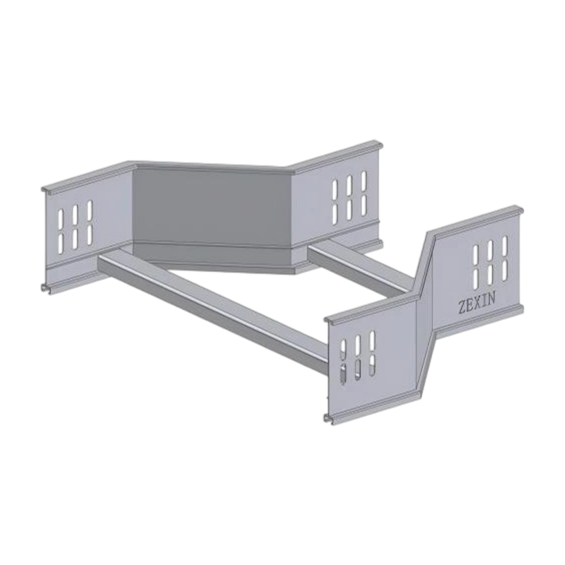 Width Reducer for Ladder Cable Tray TransitionsThis reducer smoothly transitions between 200 mm and 800 mm widths with a slope of ≤15°, accommodating non-standard tray sizes while maintaining load capacity, useful for custom installations.View Product → reducer production capability can deliver non-standard widths without compromising the load rating. It is also worth asking about OEM and ODM flexibility when the design is unique.
Final Inspection and Common Mistakes
Before energizing the system, verify that every support is tight, all connecting hardware is installed, and no tray segment is dislodged. Check that the cable tie-wrap spacings follow the cable routing guidelines. A common mistake is using cable tray as a walkway or a support for other utilities; this creates a point load that can bend the ladder. Another frequent issue is placing too many cables in a narrow ladder, which makes the cable bundle difficult to maintain and increases the risk of overheating.
If your team needs guidance on a specific installation, reach out to our engineering team. They can review your layout, confirm the fitting schedule, and point out potential problems before they become on-site delays.
Related Products
-
-
Cable ladder straight adopts a ladder-type main beam structure with crossbar support. This structure is derived from the mechanical principle of traditional I-beams. The main beam bears the weight of ...
READ MORE -
The core design of the cable ladder reducer is a trapezoidal gradual transition structure. The structure adopts a ladder-type bridge beam body, and the bottom is supported by a crossbar to ensure the ...
READ MORE -
Cable ladder cross adopts a cross-reinforced structural design. This structure achieves uniform distribution of bridge force through precise alignment of the four-way crossbars. Each crossbar is on th...
READ MORE
Related News
-
1.Choosing the Right Cable Trunking Type Cable trunking systems are solutions used to protect cables and ensure their sa...
READ MORE -
Introduction to Wire Mesh Cable Trays What are Wire Mesh Cable Trays? A wire mesh cable tray, also called a wire cable t...
READ MORE -
The Role of Perforated Cable Tray in Solar Power System Wiring Understanding Perforated Cable Trays and Their Functional...
READ MORE -
Cable Trunking: A Key Component in Reducing Electrical Hazards Electrical installations are an essential part of any mod...
READ MORE
Customized service
Customized service
Customized service
Customized service

Telephone consultation
The consultation form is here.
+86-182-6255-8899Working hours 8:00~17:00
-
Address
No. 67 Yongsheng Line, Yangzhong City, Jiangsu Province, China
XIN ZEXIN ELECTRIC PTE LTD
Email: sales@xinzexin.com.sg
Contact: +65 6214 6888
Address: 1 Sunview Road, #03-22 Eco-Tech@Sunview, Singapore 627615 -
E-mail
sales@zexinelectric.com
-
Friendship Link
www.zexin.com
-
Social Media Account
We welcome you to visit and inspect our company on site. Looking forward to becoming your partner.
CONTENTS
Copyright 2025 JIANGSU ZEXIN ELECTRIC TECHNOLOGY CO.,LTD. All Rights Reserved
