


 English
 عربى
 Français
 Español
 Português
Cable tray straight adopts a coverless U-shaped straight section design, and the overall structure is simple and practical. Its core structure is a U-shaped trough, and the edges on both sides are des...
READ MORECable Tray for Wind Turbines: Nacelle, Tower and Offshore Selection Guide
A wind turbine is a power station on a tower, and almost every kilowatt it produces travels through cable before it reaches the grid. A cable tray for wind turbines is the quiet structure that keeps those cables organised — from the pitch drives in the hub, through the nacelle, down the tower and out to the transformer and the collector network. When it is designed well, nobody notices it for twenty-five years. When it is not, it becomes a maintenance problem in the hardest place to reach.
Jiangsu Zexin Electric Technology has been manufacturing cable trays since 2016 from our factory in Yangzhong, Jiangsu Province. We build cable ladder, cable trunking, FRP cable tray, marine cable tray, perforated cable tray and wire mesh cable tray, together with the elbows, tees, crosses and reducers that turn a set of parts into a continuous route. Wind and marine work sits close to the centre of what we do, because both demand the same things: corrosion resistance, vibration tolerance and a system that can still be inspected and repaired in a confined space.
This guide collects what we have learned on the shop floor and on site. It follows the cable route through a turbine, looks at which tray family suits each zone, compares materials for onshore and offshore duty, and lists the design details that decide whether an installation still looks new after a decade of turning in the wind.
2016Manufacturing cable trays since
6Tray families in production
100+Countries served
OEM/ODMBuilt to customer drawings
Why a Wind Turbine Is a Hard Place for a Cable System
A turbine is not a static building. It is a machine that moves, vibrates, flexes and sits in weather for decades. The cable support system has to survive all of that without being looked at very often, because access is expensive and, offshore, sometimes impossible for weeks at a time. Two things usually go wrong on a poor installation: the tray itself corrodes or works loose, and the cables inside it are allowed to move more than they should.
What the environment does
- Continuous vibration from the rotor, gearbox and generator
- Temperature swings that can run from deep frost to a hot nacelle in summer
- Salt spray, humidity and condensation offshore; dust and UV onshore
- Yaw rotation that twists the cable bundle at the tower top
- Very little room, and very little light, for inspection
- A design life measured in decades, not seasons
What the tray has to do about it
- Stay fixed and rattle-free under constant vibration
- Hold its coating or resin performance across the full temperature range
- Drain and ventilate so water and heat do not collect
- Let cables move in a controlled way where the nacelle rotates
- Fit the narrow spaces between platforms, ladders and tower walls
- Be checkable with a torch and a hand, not a full dismantling
The practical conclusion is that a wind turbine tray system is designed around access and durability first, and around price second. A tray that is fifty percent cheaper but needs replacing halfway through the turbine's life is not a saving.
Following the Cable Route Through a Turbine
Cables in a turbine are not one continuous run; they pass through several distinct zones, and each zone has its own constraints. Walking the route from top to bottom is the fastest way to decide where each tray type belongs.
-
Hub and pitch system
Small power and control cables run out to the pitch motors and back to the hub controller. Space is extremely limited, bending radii are tight, and the tray is often a narrow perforated or wire mesh section fixed to the hub frame.
-
Nacelle
This is the busiest area: generator to converter, yaw drives, cooling fans, sensors and the transformer if it is mounted up top. Heat dissipation matters, so ladder and perforated trays are common, and spans have to carry the weight of heavy power cores without sagging.
-
Tower top and the twist zone
Where the nacelle yaws, the cable bundle has to accommodate rotation. The cables are arranged in a loop with controlled slack, supported so they do not rub against each other, and guided into the vertical descent. This is the part of the route that most often causes problems when it is treated casually.
-
Tower body
Long vertical runs carry the main power cables, control cables and fibre. Here the tray is usually a ladder or a closed trunking section, fixed to brackets on the tower wall, with vertical cable support at intervals so the cable weight does not hang on the top termination.
-
Tower base and foundation
The route transitions from vertical tray to buried ducts, trenches or a cable basement. Water ingress, earthing continuity and the interface between tray and duct are the details that matter most at this level.
-
Collector network and substation
Between turbines, cables are normally buried, but the onshore substation or offshore platform that collects the power uses tray and ladder systems extensively, often with higher fault-current and fire-performance requirements.
Mapping the route this way also makes the fittings list obvious. Each change of direction needs an elbow, each branch needs a tee, and each change of width needs a reducer — which is exactly how our own product families are organised.
Which Tray Family Fits Which Zone
There is no single correct tray for a wind turbine. The right answer is a small family of products, each doing a specific job along the route.
Cable ladder
Open rungs give excellent ventilation and easy cable tying. Well suited to nacelle power runs and tower verticals where heat and heavy cables dominate.
Cable trunking
A closed or semi-closed section that shields cables from dust, water and accidental contact. Useful in tower bases and where mechanical protection is required.
Perforated tray
Solid enough to support and protect, but perforated for airflow and drainage. A good general-purpose choice through the nacelle and along platform edges.
FRP cable tray
Composite construction for coastal, offshore and chemically aggressive sites. Light, non-magnetic and free of the rust cycle that affects steel.
Marine cable tray
Heavier-duty sections built for vessels and offshore structures, where vibration and salt loading are continuous rather than occasional.
Wire mesh cable tray
Light, flexible and quick to install with simple cut-and-bend field adjustments. It is often the practical choice in the hub, in control cabinets and in retrofit work where the route is irregular and the cable load is modest. Its open structure also makes visual inspection of the cables very easy, which is worth a great deal in a place that is difficult to reach.
Material Selection: Onshore, Offshore and Everything Between
Material choice is where a wind project's budget and its service life argue with each other. Onshore sites with normal rural atmospheres can use hot-dip galvanised steel for decades without trouble. Coastal and offshore sites change the calculation completely, because salt and humidity attack the coating first and the steel underneath second.
| Material | Typical wind use | Corrosion resistance | Relative weight | Practical notes |
|---|---|---|---|---|
| Hot-dip galvanised steel | Tower interior, onshore substations | Good | Heavy | Economical and widely available; coating must be undamaged at cut edges |
| Stainless steel 316L | Offshore nacelle, splash zone, platform deck | Excellent | Heavy | Highest material cost, but the safest answer where salt is always present |
| FRP / GRP | Coastal towers, offshore, chemically exposed areas | Very good | Light | Non-magnetic and non-conductive; needs closer support spacing |
| Aluminium | Weight-sensitive topside runs | Good | Lightest | Must be isolated from steel fixings to avoid galvanic corrosion |
| Painted or powder-coated steel | Protected indoor nacelle areas | Moderate | Heavy | Coating has to survive constant vibration; touch-up on site is difficult |
A frequent compromise on offshore projects is to use stainless or composite in the nacelle and splash-zone areas, and galvanised steel lower down where the atmosphere is drier and inspections are easier. As long as the transition points are detailed properly, mixing materials is perfectly workable.
Tray Families We Build for Wind Applications
Our product range is organised the way a site actually buys: a straight section for the run, plus the fittings that handle every turn, branch and width change. Three families come up most often in wind and marine conversations.
Cable ladder
The workhorse for nacelle and tower runs. We produce the straight section plus horizontal 90-degree elbows, tees, crosses and reducers, so a single order can cover the whole route without gaps in the support system.
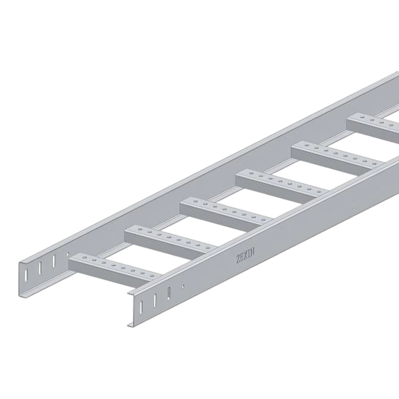 Cable Ladder Racks for Nacelle and Tower RoutesOpen-frame cable ladder racks with straights, elbows, tees, crosses and reducers for heavy-duty power, data and communication cable runs.View Product →
FRP cable tray
Composite trays for coastal and offshore duty, where steel coatings eventually lose the fight. The range covers straights, elbows, tees, crosses and reducers in the same fitting logic as the steel families.
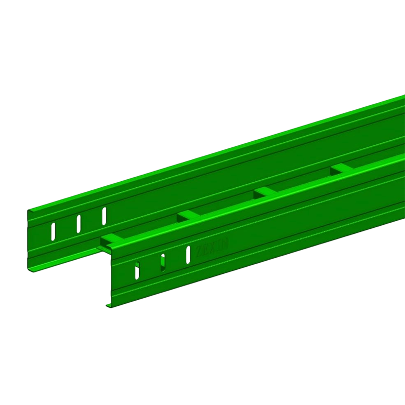 FRP Cable Trays for Corrosive Coastal and Offshore DutyFiberglass-reinforced plastic trays resist saltwater, acids and alkalis, offering lightweight, non-conductive cable management for harsh environments.View Product →
Marine cable tray
Heavier sections intended for vessels and offshore structures, available as single and double straight forms. These suit continuous vibration and salt exposure, including deck and platform cable routes.
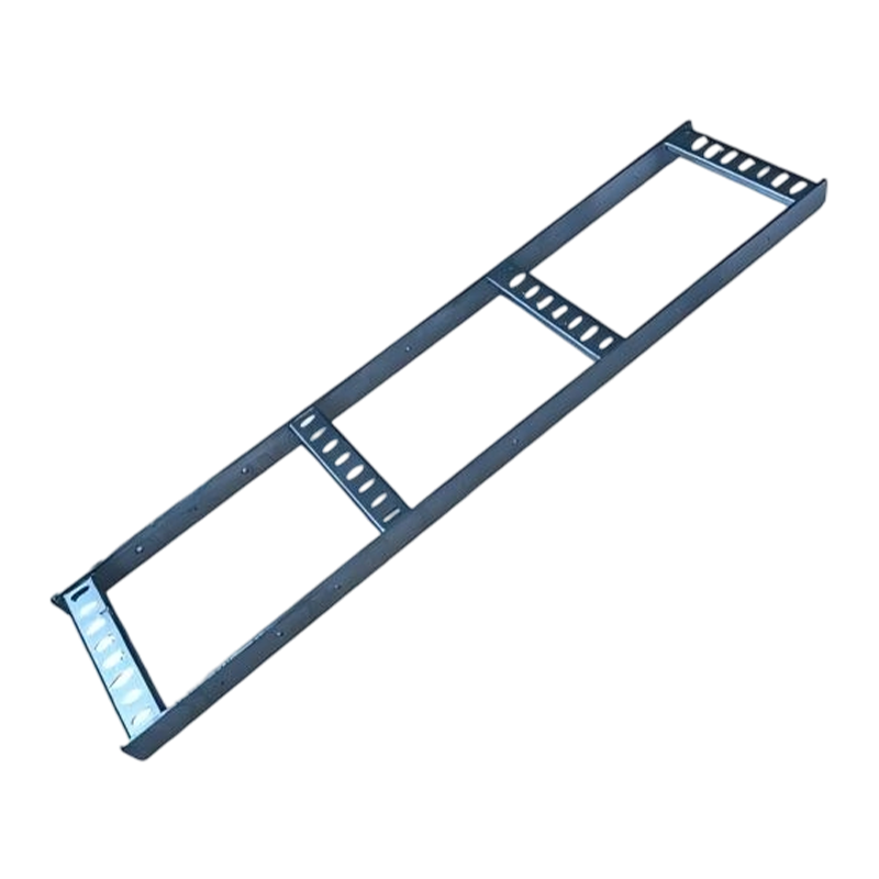 Marine Cable Tray for Ships and Offshore PlatformsHeavy-duty single and double straight trays in stainless steel or hot-dip galvanized steel, built for saltwater, vibration and confined marine spaces.View Product →
Perforated tray, trunking and wire mesh tray complete the picture. In practice, most wind projects end up mixing two or three families along one route, and the fittings list is what makes that practical.
Details That Decide Whether the Installation Lasts
Most tray failures we see are not material failures. They are detail failures — a missing support, an unsupported drop, an earthing link left out. These are the points worth checking on any turbine installation.
Support spacing and load
Spacing follows the tray's span rating and the cable load, not habit. Nacelle runs carrying heavy power cores need shorter spans than a control-only route.
Vertical cable support
Cables in a tower must be clamped or supported at intervals so their own weight does not hang on the top termination. This is one of the most common omissions.
Expansion and movement
Long external runs move with temperature. Slotted fixings and expansion joints keep the tray from buckling or pulling its brackets out of the wall.
Earthing continuity
Every joint needs a reliable conductive path, or a separate earth conductor. Painted and composite systems need particular attention here.
Brackets and fixings
The bracket is the part that carries the whole system. Different bracket types suit different wall conditions and loads, and choosing the wrong one undermines everything above it. If you want a plain-language breakdown of the options, our article on cable tray bracket types and their uses covers the common configurations.
Ventilation and drainage
Open rungs, perforations and drainage holes keep heat and water moving. Covers should be used where protection is needed, not as a default.
Working With a Manufacturer on a Wind Project
Wind projects rarely arrive with a finished drawing set. More often, a contractor or EPC has a route concept, a cable schedule and a delivery date, and needs a supplier who can turn that into a shippable parts list. Our process is built around that reality.
- Share the route layout, cable schedule and environment data — onshore, coastal or offshore.
- Agree the material and finish, and confirm which zones get which specification.
- Build the fittings list: straights, elbows, tees, crosses and reducers, with quantities.
- Check a sample or first article before full production where the geometry is unusual.
- Produce, pack for sea freight and prepare the export documentation.
- Support installation with drawings, and stay available afterwards for maintenance queries.
We also work as an OEM/ODM partner, producing to customer drawings and specifications under the customer's own brand where that suits the supply chain. Our products have gone to customers in more than a hundred countries, with particular experience in Southeast Asia, Africa and South America, and the kind of work we support — semiconductor facilities, data centres, pharmaceutical plants and solar farms — is visible in our project portfolio.
Talk to us about your next turbine route. Send drawings, a cable schedule or even a marked-up sketch, and we will come back with a material recommendation and a fittings list. You can reach our team at sales@zexinelectric.com, by phone during office hours (08:00–17:00), or through the enquiry form on the contact page. International partners are welcome to visit the factory in Yangzhong, Jiangsu, to see the machining, polishing and inspection lines in person.
Frequently Asked Questions
What width of cable tray is normally used inside a wind turbine tower?
It depends on the cable schedule, but tower runs commonly fall between 100 mm and 600 mm wide, with 300–400 mm a practical middle ground on many projects. The deciding factors are the number of power cores, the bending radius they need, and whether control and fibre share the same route. Where space is tight, two narrower trays on separate brackets often beat one wide tray.
Should I choose galvanised steel or stainless steel for an offshore turbine?
Inside the tower, hot-dip galvanised steel is still common where humidity can be managed. For the nacelle exterior, splash zones and any area with continuous salt spray, 316L stainless steel or a composite tray is the safer answer. The cost difference is real, but so is the cost of replacing a tray forty metres up a tower.
Can FRP cable tray be used in a nacelle?
Yes, and it is often sensible. FRP is light, non-magnetic and does not rust. The trade-offs are lower stiffness over long spans, so supports need to be closer together, and fire performance has to be checked against the project's safety requirements.
How often should vertical cables be supported in a tower?
Vertical runs should be clamped or supported at regular intervals so cable weight does not hang on the top termination. The exact spacing comes from the cable manufacturer's data and the project specification. Shorter spans are always safer, and the cost of a few extra cleats is small compared with a failed termination.
Do you produce custom fittings for tower penetrations and platform edges?
Yes. Straights, horizontal 90-degree elbows, tees, crosses and reducers cover most of a route, and we can produce non-standard angles, widths and bracket arrangements from drawings. Send a route layout or a marked-up sketch and we will confirm what needs to be custom-made.
What information do you need in order to quote a wind project?
The route layout, tray width and material, expected cable load, environment (onshore, coastal or offshore), surface finish, quantity of fittings and the delivery port. If the drawings are not final, a rough route sketch and a cable schedule are enough to start the conversation.
A cable tray for wind turbines is a modest part of a very expensive asset, which is exactly why it deserves more than a line on a bill of materials. Get the material right for the environment, get the fittings list complete, and get the supports and clamps detailed properly, and the cable system will quietly do its job for the life of the turbine.
If you are at the stage where the route is still a sketch, that is a good time to talk. Our engineering team can review the layout, suggest where a different tray family would serve you better, and turn the concept into a complete list of standard and custom parts ready for production.
Related Products
-
-
Cable ladder straight adopts a ladder-type main beam structure with crossbar support. This structure is derived from the mechanical principle of traditional I-beams. The main beam bears the weight of ...
READ MORE -
Conservation cable tray straight is made of high-quality cold-rolled steel and aluminum alloy as the main materials. Cold-rolled steel provides a solid support foundation for the bridge with its good ...
READ MORE -
The core design of the cable ladder reducer is a trapezoidal gradual transition structure. The structure adopts a ladder-type bridge beam body, and the bottom is supported by a crossbar to ensure the ...
READ MORE
Related News
-
1.Choosing the Right Cable Trunking Type Cable trunking systems are solutions used to protect cables and ensure their sa...
READ MORE -
Introduction to Wire Mesh Cable Trays What are Wire Mesh Cable Trays? A wire mesh cable tray, also called a wire cable t...
READ MORE -
The Role of Perforated Cable Tray in Solar Power System Wiring Understanding Perforated Cable Trays and Their Functional...
READ MORE -
Cable Trunking: A Key Component in Reducing Electrical Hazards Electrical installations are an essential part of any mod...
READ MORE
Customized service
Customized service
Customized service
Customized service

Telephone consultation
The consultation form is here.
+86-182-6255-8899Working hours 8:00~17:00
-
Address
No. 67 Yongsheng Line, Yangzhong City, Jiangsu Province, China
XIN ZEXIN ELECTRIC PTE LTD
Email: sales@xinzexin.com.sg
Contact: +65 6214 6888
Address: 1 Sunview Road, #03-22 Eco-Tech@Sunview, Singapore 627615 -
E-mail
sales@zexinelectric.com
-
Friendship Link
www.zexin.com
-
Social Media Account
We welcome you to visit and inspect our company on site. Looking forward to becoming your partner.
CONTENTS
Copyright 2025 JIANGSU ZEXIN ELECTRIC TECHNOLOGY CO.,LTD. All Rights Reserved
