


 English
 عربى
 Français
 Español
 Português
Cable tray straight adopts a coverless U-shaped straight section design, and the overall structure is simple and practical. Its core structure is a U-shaped trough, and the edges on both sides are des...
READ MORECable Tray for Renewable Energy Facilities: Selection and Installation Guide
Walk a solar farm or a wind site for the first time and the thing that surprises most people is not the panels or the turbines. It is the sheer volume of cable running between them. Renewable energy facilities generate power in many small, distributed units and then collect it into inverters, transformers and substations. That means long, repetitive cable routes, often outdoors, often in coastal or desert conditions, and almost always exposed to sun, rain and temperature swings. Cable tray for renewable energy facilities is therefore not a minor accessory. It is the structure that keeps those routes organised, protected and maintainable for the twenty-five years the asset is expected to run.
Why Renewable Energy Sites Need a Different Cable Tray Approach
A conventional factory usually concentrates its electrical loads in one or two rooms. A renewable energy facility spreads them across hectares. A 50 MW solar farm may have hundreds of string runs, dozens of combiner boxes and several inverter stations, all linked by cable that must be carried above ground, above a roof membrane or along a turbine tower. Wind farms add long collection circuits between turbines. Battery storage compounds add dense DC and control cabling in a very small footprint.
That layout creates a consistent set of demands:
- Long, repetitive routes where installation speed and consistent support spacing matter more than elaborate detailing.
- Permanent outdoor exposure, including UV, salt spray, sand, driving rain and in some regions heavy snow.
- Wide temperature swings, which move metal and change the behaviour of cable insulation over time.
- Access for inspection and thermal imaging, because faults in a PV array are far easier to find when cables are visible rather than buried.
- A service life that matches the asset, usually 20 to 30 years, without a repainting programme.
None of these points are exotic, but together they push the specification toward open, corrosion-resistant and easily extendable systems rather than closed, decorative ones.
Comparing the Tray Types Most Often Specified
The table below is a rough starting point. The right answer still depends on the site, the cable sizes and the local code, but this is how the main families usually sort out.
| Tray Type | Typical Renewable Application | Why It Works |
|---|---|---|
| Cable ladder | Power collection runs, substations | Open rungs give ventilation and easy clamping for large power cables |
| Perforated tray | Rooftop and ground-mount PV string wiring | Punched base drains water and allows ties almost anywhere |
| Wire mesh tray | Storage rooms, inverter and control buildings | Light, flexible and fast to route around obstacles |
| FRP tray | Coastal, chemical and highly corrosive sites | No metal to rust and no conductive path |
| Cable trunking | Indoor switch rooms and equipment enclosures | Enclosed profile shields cable from dust and contact |
| Marine tray | Offshore wind, floating solar, port facilities | Built for vibration and salt spray near the water |
The Tray Families We Build for Renewable Projects
We have been manufacturing cable tray in Yangzhong, Jiangsu since 2016, and renewable work now makes up a good share of what leaves our factory. Three product families come up again and again.
Cable Ladder for Power Collection Runs
Where heavy power cables leave inverters, transformers and substations, an open ladder gives ventilation, easy clamping and room for the generous bend radii those cables need. Rungs are commonly set at 250 or 300 mm, and the side rails carry load across several metres when supports are planned carefully. It is the least fussy way to handle big conductors outdoors.
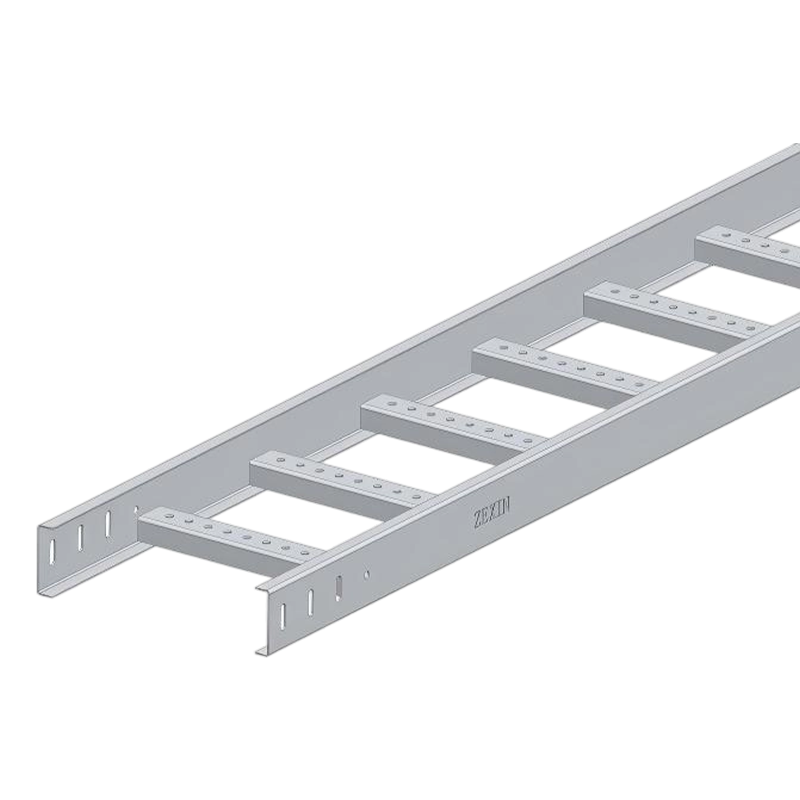 Cable Ladder Straight for Heavy Power Cable RoutesOpen ladder-type tray for inverter, transformer and substation runs, supporting large cables with ventilation, clamping space and up to 200 kg/m load.View Product →
Perforated Tray for Solar String and Rooftop Work
On rooftop and ground-mount PV, perforated tray is often the practical middle ground. The punched base lets rainwater drain away, allows airflow beneath the cables and gives the installer freedom to tie at almost any point. It also keeps DC string wiring visually ordered, which pays off during commissioning and later fault finding. Straight sections and matching bends are usually enough to cover an entire array.
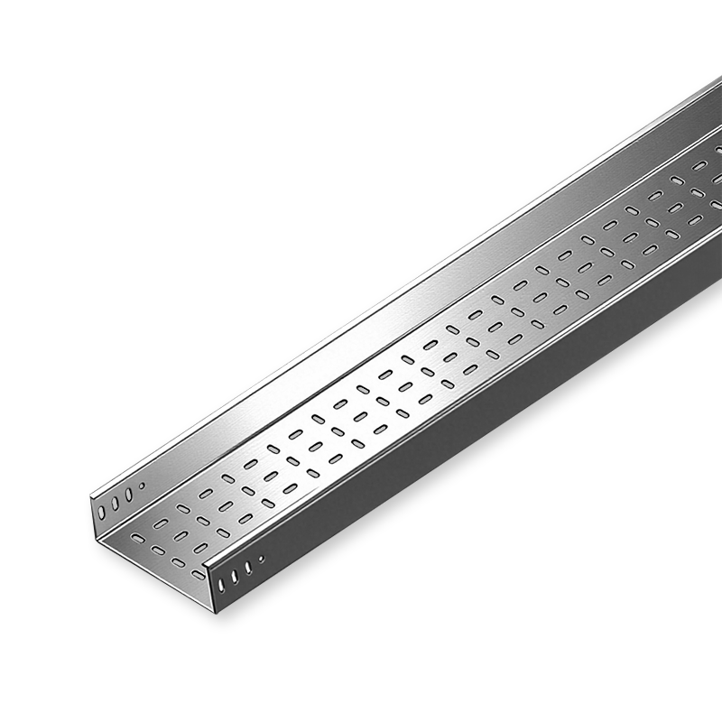 Perforated Cable Tray Straight for Solar PV WiringOpen perforated tray with drainage and airflow for rooftop or ground-mount PV, offering modular assembly and widths from 100 mm to 1000 mm.View Product →
FRP Tray Where Corrosion Rules
Coastal solar farms, offshore platforms and sites close to chemical plants can shorten the life of a painted steel system surprisingly quickly. FRP tray removes the problem at its source because there is no metal to rust, and it is non-conductive, which some operators prefer in particular DC areas. It costs more up front and saves the argument about repainting later.
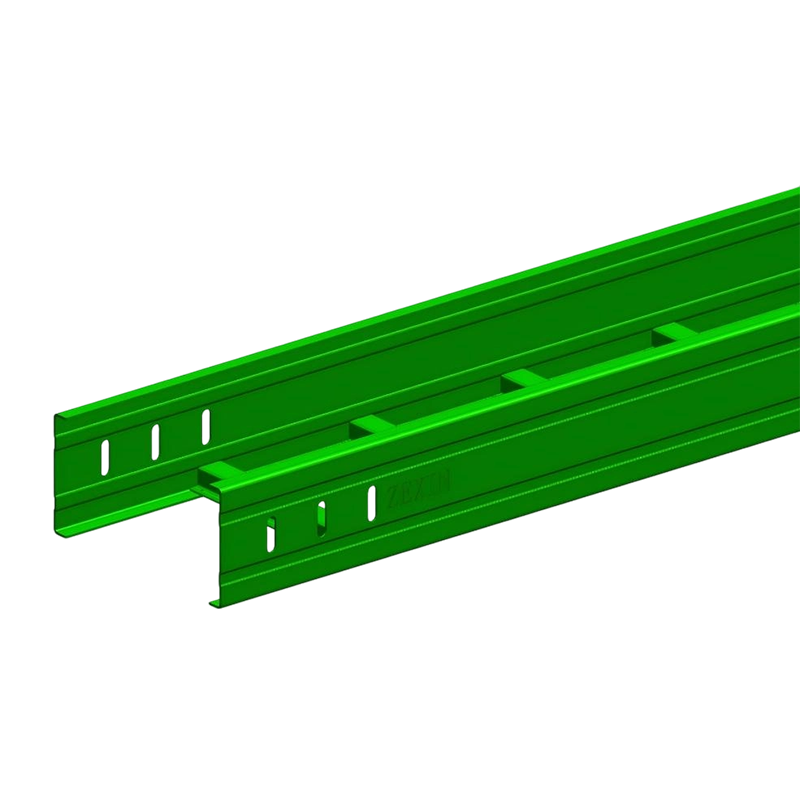 FRP Cable Tray Straight for Corrosive Coastal SitesNon-conductive, flame-retardant FRP tray for offshore, chemical and coastal installations where rust resistance and electrical insulation matter.View Product →
Wire mesh tray and enclosed trunking also have their place, usually for short internal runs in inverter stations and control buildings where light weight and a tidy appearance matter more than span strength.
Design Details That Decide Whether the System Lasts
Most failures we see discussed are not dramatic. They come from small details that were skipped at design stage. A few worth checking on every project:
- Thermal expansion. Long straight runs outdoors need expansion joints or slip connections, typically every 30 metres or as the manufacturer directs, otherwise the tray buckles at a fixed support.
- Support spans and load. Cable weight, wind uplift on exposed roofs and snow accumulation should all be considered, not only the tray's own weight.
- Earthing continuity. Where the tray is used as part of the protective conductor path, joints need bonding jumpers or listed connection hardware, and the route must be tested at handover.
- Cable grouping and derating. Filling a tray tightly changes heat dissipation, and DC strings are especially sensitive to this in hot climates.
- Cut edges and touch-up. Every field cut in a galvanised or painted system should be treated, because that is where corrosion starts.
- Clearance and access. Leaving a walkway or inspection gap saves hours later when a thermal camera has to scan the array.
If your project is PV specific, our article on the role of perforated cable tray in solar power systems goes deeper into string layout and drainage.
Installation Practice on Site
The sequence below is the one we recommend to installation crews, and it keeps rework low on large sites.
- Survey the route and mark support positions before any tray arrives, accounting for expansion joints and building movement joints.
- Set brackets and supports to a consistent line, since a wandering tray is difficult to align later and looks careless to an inspector.
- Install straight sections first, then fit elbows, tees, crosses and reducers where the route actually turns.
- Bond each joint as specified and record the readings before cables are pulled.
- Pull cable with rollers at every change of direction so insulation is not scraped on side rails or rung edges.
- Fix cables at the specified intervals, leaving enough slack for thermal movement and future termination work.
What Real Project Experience Adds
Renewable work rarely stands alone. A manufacturer who has supplied solar, storage and industrial facilities tends to notice the details that a general supplier misses, such as how a photovoltaic roof project needs different drainage thinking from a data hall. You can see a sample of the projects we have supplied on our site, including JTC Solar Roof 2 and Solar Nova 5 in Singapore, semiconductor and pharmaceutical builds, and a data centre fit-out. Each one taught us something about finish selection, packing and delivery timing that we now build into quotations as standard.
Working With a Manufacturer on Your Specification
Because we produce the tray ourselves rather than reselling it, non-standard lengths, hole patterns, finishes and OEM labelling are all workable. If you are preparing a tender package, these are the points worth confirming early:
- The finish you actually need, whether pre-galvanised, hot-dip galvanised, stainless steel or FRP, and the environment it will face.
- Load and span requirements, including any local wind or snow data.
- Whether the tray forms part of the earthing path and what bonding hardware is required.
- Delivery schedule against your installation sequence, since renewable sites often build in phases.
Send us your drawings or a specification list and we will come back with a straightforward proposal, including the accessories needed for a complete route rather than a partial one. That is the part of the job we enjoy most: turning a complicated cable layout into something the crew can install quickly and the client can live with for decades.
Related Products
-
-
Cable ladder straight adopts a ladder-type main beam structure with crossbar support. This structure is derived from the mechanical principle of traditional I-beams. The main beam bears the weight of ...
READ MORE -
Conservation cable tray straight is made of high-quality cold-rolled steel and aluminum alloy as the main materials. Cold-rolled steel provides a solid support foundation for the bridge with its good ...
READ MORE -
The core design of the cable ladder reducer is a trapezoidal gradual transition structure. The structure adopts a ladder-type bridge beam body, and the bottom is supported by a crossbar to ensure the ...
READ MORE
Related News
-
1.Choosing the Right Cable Trunking Type Cable trunking systems are solutions used to protect cables and ensure their sa...
READ MORE -
Introduction to Wire Mesh Cable Trays What are Wire Mesh Cable Trays? A wire mesh cable tray, also called a wire cable t...
READ MORE -
The Role of Perforated Cable Tray in Solar Power System Wiring Understanding Perforated Cable Trays and Their Functional...
READ MORE -
Cable Trunking: A Key Component in Reducing Electrical Hazards Electrical installations are an essential part of any mod...
READ MORE
Customized service
Customized service
Customized service
Customized service

Telephone consultation
The consultation form is here.
+86-182-6255-8899Working hours 8:00~17:00
-
Address
No. 67 Yongsheng Line, Yangzhong City, Jiangsu Province, China
XIN ZEXIN ELECTRIC PTE LTD
Email: sales@xinzexin.com.sg
Contact: +65 6214 6888
Address: 1 Sunview Road, #03-22 Eco-Tech@Sunview, Singapore 627615 -
E-mail
sales@zexinelectric.com
-
Friendship Link
www.zexin.com
-
Social Media Account
We welcome you to visit and inspect our company on site. Looking forward to becoming your partner.
CONTENTS
Copyright 2025 JIANGSU ZEXIN ELECTRIC TECHNOLOGY CO.,LTD. All Rights Reserved
