


 English
 عربى
 Français
 Español
 Português
Cable tray straight adopts a coverless U-shaped straight section design, and the overall structure is simple and practical. Its core structure is a U-shaped trough, and the edges on both sides are des...
READ MORECable Tray for Oil and Gas Facilities: Materials, Routing, and Installation Guide
Oil and gas facilities ask far more of their cable management systems than a typical commercial building does. An offshore platform washes every support with salt spray from the day it is commissioned. A refinery or petrochemical unit carries hydrogen sulfide, hydrocarbon vapours and caustic washdown water through the same racks that hold power feeders to motors, switchgear and compressors. A desert gas plant swings between intense daytime heat and cold nights, and an LNG terminal has to plan for decades of continuous service with almost no opportunity to shut a corridor down and replace anything.
That is why specifying a cable tray for oil and gas facilities is never just a catalogue exercise. The tray has to survive the project corrosion study, carry the load the electrical team calculated, fit into the routing that piping and structural disciplines left available, and pass the documentation reviews that come with an EPC contract. What follows is a practical walkthrough of the decisions that come up most often in enquiries and project drawings, written from the perspective of a manufacturer that builds these systems every day.
What Makes Cable Tray Different in Oil and Gas Service
Several factors separate oil and gas projects from general industrial work, and they tend to appear together rather than one at a time.
- Aggressive atmospheres. Chlorides, hydrogen sulfide, sulphur dioxide and process chemicals attack both the tray surface and the fasteners that hold it together.
- Hazardous area classification. Zoned areas influence material choices, installation practice and the way trays are bonded and earthed.
- High cable density. Large power feeders run alongside control, instrumentation and fibre optic cables, often in the same corridor, which makes segregation planning essential.
- Long service life with limited maintenance windows. Once a plant is running, access to a tray run may require permits, scaffolding and shutdown time.
- Documentation. Material certificates, inspection and test plans, load data and drawings are part of the deliverable, not an afterthought.
Each of these points nudges the specification in a different direction, which is why the material and tray type usually get decided together rather than in sequence.
Matching the Tray Material to the Service Environment
The corrosion study is normally the document that settles the material question, and it is worth reading it against the actual location of each run. Decks, splash zones, tank farms and sheltered analyser houses on the same site can justify different answers.
| Material | Typical Service Environment | Relative Corrosion Resistance | Practical Notes |
|---|---|---|---|
| Hot-dip galvanized steel | Sheltered onshore units, pipe racks, utility areas | Moderate | Widely available and economical; cut edges and site drillings need repair |
| Stainless steel | Offshore decks, chloride or H2S exposure, washdown areas | High | Higher cost and slower fabrication; attention needed at dissimilar metal contacts |
| FRP (glass reinforced plastic) | Coastal, chemical and strongly corrosive zones | High, non-metallic | Light and non-conductive; fire performance and UV exposure must be verified |
| Aluminium | Weight-sensitive topsides and long spans | Moderate to good | Light to handle, but not suitable for every chemical exposure |
Where corrosion resistance is the deciding factor, glass reinforced plastic trays are often chosen for the most exposed runs because they combine chemical resistance with low weight, which reduces the load the structural steel has to carry.
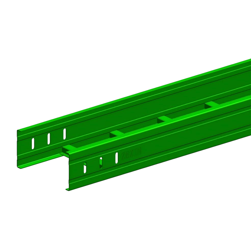 FRP Cable Tray Straight Sections for Corrosion-Resistant Cable RunsStraight glass fiber reinforced plastic tray sections offer chemical resistance, low weight, electrical insulation, and a smooth interior for protecting cables in exposed installations.View Product →
Tray Types and Where Each One Fits
Cable ladder
Ladder tray remains the workhorse for power distribution in process plants. The open rungs allow heat to dissipate from heavily loaded feeders and make it easy to drop cables out at a motor or a junction box. A complete run is assembled from straight sections plus horizontal elbows, tees, crosses and reducers, so the routing can follow the pipe rack without custom fabrication at every turn.
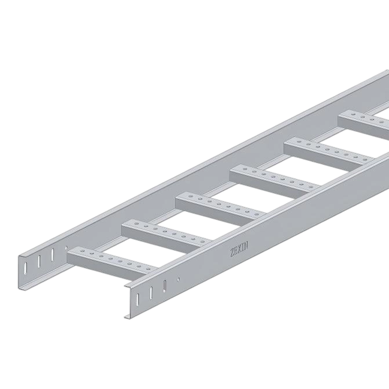 Cable Ladder Straight Sections for High-Load Power DistributionOpen ladder straight sections support high-density power cable runs, using crossbar main beams for strength, ventilation, and up to 200 kg/m load capacity.View Product →
Cable trunking
Where instrumentation, control and communication cables need mechanical protection, closed trunking with a lid keeps dust, spray and accidental contact away from the conductors. In oil and gas work it is frequently used for the signal side of the plant, running alongside but separated from the power ladder.
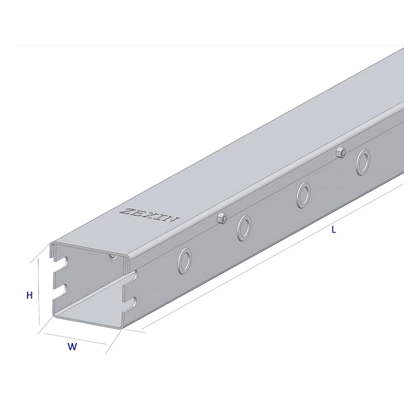 Cable tray straightTrough-type, tray-type straight sections standard dimensions (mm):: 50 × 50 100 × 50 100 × 100 150 × 100 200 × 100 300 × 100View Product →
Perforated and wire mesh trays
Perforated trays offer a middle ground, giving partial enclosure while still allowing airflow and easy cable entry. Wire mesh trays are lighter again and suit dense, low-load cable populations such as telecom and control rooms. Both are usually specified for the lighter end of the plant rather than for main power feeders.
Load, Span and Support Detailing
Load calculations for oil and gas work rarely stop at the weight of the cables. Wind on an open rack, snow in cold climates, ice on exposed structures, thermal expansion over long straight runs and seismic requirements all appear in project specifications. A tray that is adequate on paper can still deflect beyond its limit if the support spacing is stretched to suit a congested steel layout.
The practical answer is to design the support system at the same time as the tray itself. The cable tray brackets and cantilevers, their fixing method to the primary steel, and the spacing between them determine how the run behaves under full load. Where a run passes through a fire wall, changes direction, or expands between two fixed points, that detail deserves its own drawing rather than being left to the installation crew.
Routing, Segregation and Earthing
Segregation is one of the most common review comments on oil and gas submittals. Power and instrumentation cables should not share the same tray unless the specification explicitly allows it, and where they run in parallel the separation distance needs to be stated and maintained. Crossings should be kept at right angles, and spare capacity should be planned into the tray width so future cables do not force a new run.
Earthing continuity matters just as much. Tray sections are bonded so that the system provides a continuous path, and the bonding method has to remain effective after the surface treatment and after site modifications. In classified areas, installation crews also work to spark-free practices, which affects tooling and how sections are cut and drilled on site.
Corrosion Details That Are Usually Missed
Most premature failures on tray systems start at a detail rather than in the middle of a straight section. Cut ends that were never repaired, drilled holes that exposed bare steel, stainless fasteners threaded into galvanized brackets, water that collects in a support channel, or a tray resting directly on a dissimilar metal surface all create small cells that grow over the years.
Good practice is straightforward: cut and drill before finishing where possible, repair coatings on site with the specified product, use isolation washers and gaskets at dissimilar metal interfaces, and check that drainage paths are not blocked by accessories or by the tray itself. Specifying the right material is only half of the corrosion protection story.
Documentation and Delivery for Project Buyers
For a project buyer, the tray package is judged on how easily it can be reviewed and accepted. That usually means shop drawings, load and span data, material certificates, inspection reports, and packing lists that match the way materials will be received on site. It also means a supplier who understands that a shipment to a remote site cannot be short by three elbows.
Jiangsu Zexin Electric Technology has been manufacturing cable tray systems since 2016 from its factory in Yangzhong, Jiangsu, covering ladder, trunking, perforated, wire mesh, FRP and marine tray families with the connecting components that go with each. Alongside standard production, the company works to OEM and ODM arrangements and supports projects through design, installation coordination and after-sales follow-up. A look at the portfolio of completed projects shows semiconductor, data centre, pharmaceutical and solar installations, which is a useful reminder that the same discipline that suits a cleanroom or a data hall also suits the more demanding corridors of an oil and gas plant.
A Short Checklist Before You Order
When an enquiry arrives, the answers to these questions usually determine the specification.
- What does the corrosion study say about the specific location of each run?
- Which tray type and width have been calculated for the cable population, including spare capacity?
- What support spacing does the load table allow, and who is detailing the brackets?
- How are power and instrumentation cables segregated along the route?
- How will bonding continuity and earthing be maintained across joints and penetrations?
- What documentation, certificates and packaging does the project require?
Get these right early, and the tray package stops being a procurement problem and becomes one of the parts of the project that simply works.
Related Products
-
-
Cable ladder straight adopts a ladder-type main beam structure with crossbar support. This structure is derived from the mechanical principle of traditional I-beams. The main beam bears the weight of ...
READ MORE -
Conservation cable tray straight is made of high-quality cold-rolled steel and aluminum alloy as the main materials. Cold-rolled steel provides a solid support foundation for the bridge with its good ...
READ MORE -
The core design of the cable ladder reducer is a trapezoidal gradual transition structure. The structure adopts a ladder-type bridge beam body, and the bottom is supported by a crossbar to ensure the ...
READ MORE
Related News
-
1.Choosing the Right Cable Trunking Type Cable trunking systems are solutions used to protect cables and ensure their sa...
READ MORE -
Introduction to Wire Mesh Cable Trays What are Wire Mesh Cable Trays? A wire mesh cable tray, also called a wire cable t...
READ MORE -
The Role of Perforated Cable Tray in Solar Power System Wiring Understanding Perforated Cable Trays and Their Functional...
READ MORE -
Cable Trunking: A Key Component in Reducing Electrical Hazards Electrical installations are an essential part of any mod...
READ MORE
Customized service
Customized service
Customized service
Customized service

Telephone consultation
The consultation form is here.
+86-182-6255-8899Working hours 8:00~17:00
-
Address
No. 67 Yongsheng Line, Yangzhong City, Jiangsu Province, China
XIN ZEXIN ELECTRIC PTE LTD
Email: sales@xinzexin.com.sg
Contact: +65 6214 6888
Address: 1 Sunview Road, #03-22 Eco-Tech@Sunview, Singapore 627615 -
E-mail
sales@zexinelectric.com
-
Friendship Link
www.zexin.com
-
Social Media Account
We welcome you to visit and inspect our company on site. Looking forward to becoming your partner.
CONTENTS
Copyright 2025 JIANGSU ZEXIN ELECTRIC TECHNOLOGY CO.,LTD. All Rights Reserved
